
Unlike pipe clamps, which mainly carry static weight, cable cleats have a dynamic job: they must restrain power cables against the violent electromagnetic forces produced during a short-circuit fault. When a large fault current flows through parallel conductors, the magnetic fields they produce interact and generate strong repulsion (or attraction) forces between the cables — forces that can reach thousands of newtons per metre for a short, intense period. If the cleats and their spacing are not rated for this force, the cables can be thrown apart, damaging the cables, the cleats and the supporting structure, and creating a safety hazard. This article explains how the short-circuit force arises, how to calculate the peak force per metre between conductors, and how the cleat short-circuit rating and the spacing between cleats must be selected together so the installation survives a fault. It complements the cable cleat material selection guides by focusing on the electromechanical design that drives cleat rating and spacing.
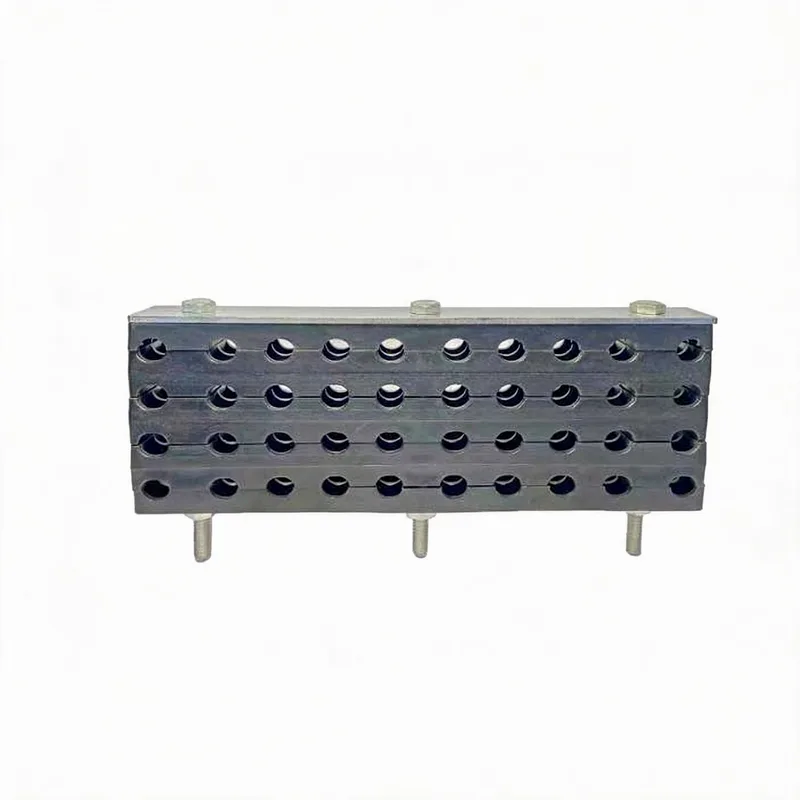
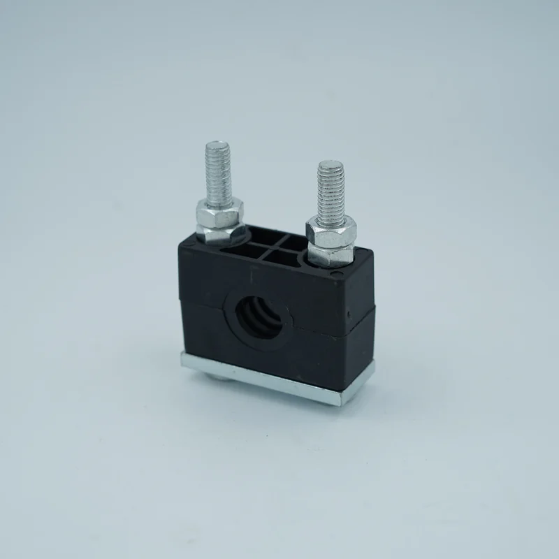
Related product photos
Key points
- Short-circuit force between two conductors is proportional to the square of the current and inversely proportional to the spacing between them
- The peak (first-cycle) force, driven by the asymmetric peak current, is the design case — it can be more than double the steady RMS-based value
- Cleat spacing must be close enough that the force per span stays within the cleat short-circuit rating — higher fault current means closer cleats
- Cleat short-circuit ratings come from type testing to IEC 61914 — use the tested rating for the actual formation (trefoil or flat), not a calculation alone
| Factor | Effect on Short-Circuit Force | Design Implication | Note |
|---|---|---|---|
| Peak short-circuit current (Ip) | Force ∝ Ip² — doubling current quadruples force | Use the prospective peak, not the RMS, as the design current | Peak ≈ 2.5 × RMS for a fully asymmetric fault |
| Spacing between conductors (s) | Force ∝ 1/s — closer cables means higher force | Trefoil (touching) cables see higher force than spaced flat | s is centre-to-centre spacing of the conductors |
| Cleat spacing (span L) | Force per cleat ∝ span length | Reduce span to bring force within cleat rating | Closer cleats = lower force each, but more cleats |
| Formation (trefoil vs flat) | Changes geometry and force distribution | Use the cleat rating tested for that formation | Trefoil cleats and flat cleats are rated separately |
The relationships above show the direction and sensitivity of each factor. The actual peak force per metre is given by the formula in the calculation section; the binding design check is always the type-tested cleat rating to IEC 61914 for the specific formation, current and spacing.
Why short-circuit current creates a mechanical force
Any current-carrying conductor produces a magnetic field around it. When two conductors carry current and lie parallel to each other, each one sits in the magnetic field of the other, and the interaction produces a mechanical force between them — this is the same Lorentz-force principle that drives an electric motor. Under normal load current the force is small and harmless. During a short-circuit fault, however, the current can rise to many times the normal load — tens of kiloamperes in a power distribution system — and because the force depends on the square of the current, it becomes enormous. For two parallel conductors, the force per unit length is proportional to the product of the two currents divided by the distance between them. In a three-phase fault all three conductors carry fault current simultaneously, so each cable experiences forces from the other two, and the direction and magnitude depend on the instantaneous currents and the geometry. The result is a sudden, violent push (and in some phase combinations, pull) that lasts for the duration of the fault — typically a fraction of a second until the protection clears it, but long enough to do mechanical damage if the cables are not restrained.
Calculating the peak force per metre
The peak force per unit length between two parallel conductors is given by F = (μ₀ / 2π) × (Ip₁ × Ip₂) / s, where μ₀/2π = 2 × 10⁻⁷ (the magnetic constant grouped), Ip is the peak instantaneous current in each conductor in amperes, and s is the centre-to-centre spacing in metres. F comes out in newtons per metre. The critical input is the peak current Ip, not the RMS short-circuit current. A short-circuit current is initially asymmetric — it has a DC offset that decays — so the first peak is much higher than the symmetrical RMS value. For a fully asymmetric fault the peak can be approximately 2.5 times the RMS symmetrical current (the exact factor depends on the X/R ratio of the circuit). Because the force depends on the square of current, using the RMS value instead of the peak would under-estimate the force by a factor of around 6. For a worked sense of scale: two conductors 100 mm apart each carrying a 50 kA peak fault current experience a force of 2 × 10⁻⁷ × (50,000)² / 0.1 = 5,000 N/m — five kilonewtons per metre, pushing the cables apart. This is why the calculation matters: the numbers are large, and they scale steeply with fault current and inversely with spacing. In a three-phase system the per-phase force is found using the standard three-phase force factors, but the single-pair formula above gives the essential physics and magnitude.
How spacing between cleats turns force into load
The force calculated above is a force per metre of cable. The load that any individual cleat must withstand depends on how far apart the cleats are spaced, because each cleat restrains the length of cable in its span. If the force is F newtons per metre and the cleats are spaced L metres apart, then the load tending to push the cable out of a cleat is on the order of F × L (the exact relationship depends on how the span is modelled, but the load scales with span length). This gives the designer a direct lever: for a given fault current and conductor spacing, reducing the distance between cleats reduces the load on each cleat. If the calculated force per metre is high — because the fault current is high or the conductors are close together — the cleats must be placed closer together so that no single cleat is asked to carry more than its rated short-circuit withstand. Conversely, on a low-fault-current circuit the cleats can be spaced further apart. This is the central design trade-off in cable cleat spacing: closer spacing means more cleats and higher installed cost but lower load per cleat, while wider spacing means fewer cleats but higher load each. The spacing is chosen so the per-cleat load stays within the cleat short-circuit rating with margin.
Trefoil vs flat formation and cleat type
Single-core power cables are installed in one of two main formations, and the formation changes both the force geometry and the type of cleat used. In trefoil formation, three single-core cables are bundled in a triangular cluster, touching or nearly touching, and held by a trefoil cleat that wraps around all three. The conductor spacing s is small (roughly the cable diameter), so the force between adjacent cables is high, but the symmetrical triangular geometry means the net force on the bundle tends to try to expand it outward. Trefoil cleats are designed to contain this outward burst and are short-circuit type-tested in the trefoil arrangement. In flat (or in-line) formation, the cables are laid side by side in a single plane, each held by a cleat that grips that cable to the support. The spacing between cables can be larger (reducing force) or the cables can touch, and the force tends to push the outer cables apart and the centre cable is pushed alternately. Flat-formation cleats are type-tested in the flat arrangement. The key point is that a cleat's short-circuit rating is specific to the formation it was tested in — a trefoil cleat rating does not directly apply to a flat installation and vice versa. Select the cleat type for the actual formation and use the manufacturer's tested rating for that formation.
IEC 61914 type testing and using rated values
Cable cleat short-circuit performance is established by type testing to IEC 61914, the international standard for cable cleats. In a type test, a sample installation of cleats holding cables in a defined formation at a defined spacing is subjected to a specified peak short-circuit current, and the cleats must retain the cables without failure. The result is a rated short-circuit withstand expressed as a peak current for a given formation and cleat spacing. This tested rating is the authoritative design value — it captures real behaviour (including dynamic effects, cleat deformation and cable movement) that a simple hand calculation cannot fully predict. The practical design process is therefore: calculate the prospective peak short-circuit current of the circuit, determine the conductor formation and spacing, and then select a cleat with an IEC 61914 short-circuit rating equal to or greater than the prospective peak current at a cleat spacing equal to or less than the tested spacing. Do not exceed the tested spacing, because a wider spacing increases the load per cleat beyond the tested condition. The hand calculation of force per metre is valuable for understanding the magnitude and sensitivity, and for sanity-checking, but the binding requirement is matching the application to a type-tested cleat rating. Always obtain the test data or rating from the cleat manufacturer for the specific product, formation and spacing.
RFQ data for short-circuit-rated cable cleats
When requesting cable cleats for a short-circuit duty, provide: the prospective short-circuit current (state whether it is RMS symmetrical or peak, and the system X/R ratio if known, so the peak can be confirmed); the system voltage; the cable outside diameter and weight per metre; the conductor formation (trefoil or flat) and the conductor centre-to-centre spacing; the required or proposed cleat spacing; the number of circuits and cables per circuit; the mounting structure and orientation; the environment (indoor, outdoor, coastal, marine, buried) for material selection; and any project specification or standard the cleats must comply with (IEC 61914 and any client-specific requirement). With this the supplier can confirm a cleat with an adequate IEC 61914 short-circuit rating for the formation and spacing, in a material suitable for the environment, and recommend the maximum cleat spacing that keeps the per-cleat load within the tested rating.
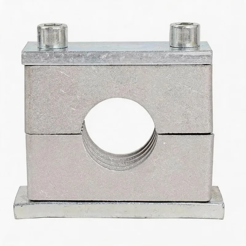
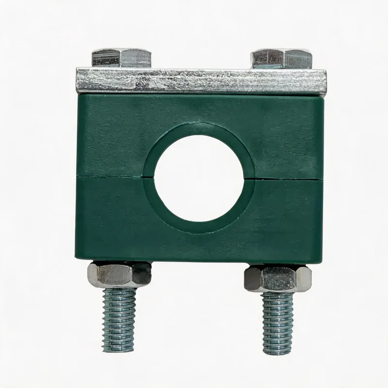
Related WeiQue series
Recommended reading
References
These pages summarize public standard metadata and industry application information. They do not reproduce the paid DIN standard text.