
Cryogenic pipework — carrying LNG (around −162 °C), liquid nitrogen (−196 °C), liquid oxygen, liquid hydrogen and other liquefied gases — places demands on pipe supports that ordinary ambient-temperature clamping does not. Three issues dominate: many common metals lose their toughness and become brittle at cryogenic temperatures, so material selection is safety-critical; cryogenic pipes contract substantially when cooled from ambient to operating temperature, so the support system must accommodate large movements; and the pipe is heavily insulated with a vapour barrier to prevent ice formation and heat ingress, so the clamp must work with thick cold insulation rather than clamping bare pipe. This article explains how these factors change pipe clamp selection and arrangement for cryogenic and LNG service, where the consequences of a support failure — a cracked clamp, a cold leak, or a brittle fracture — are far more serious than in ambient piping.
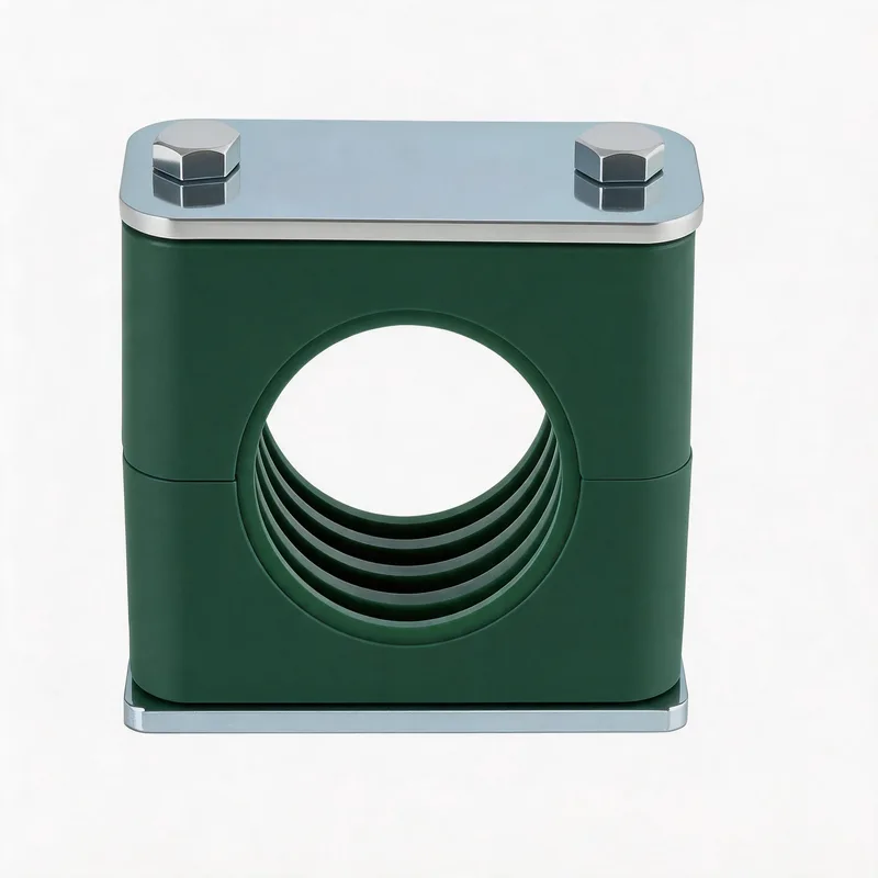
Related product photos
Key points
- Carbon steel and ferritic/martensitic stainless become brittle below their transition temperature — austenitic stainless (304/316) stays tough to cryogenic temperatures
- Cryogenic pipes contract a lot on cool-down — a 30 m stainless line cooling to −162 °C shortens by roughly 90 mm, which the support layout must absorb
- Clamps grip over the cold insulation using load-bearing insulation segments (cryogenic shoes), not the bare cold pipe — clamping bare pipe creates a thermal bridge and ice
- A vapour barrier over the insulation must remain intact at the support — any penetration lets moisture in, which freezes, expands and destroys the insulation
| Material | Low-Temp Toughness | Cryogenic Suitability | Use in Cryogenic Clamping |
|---|---|---|---|
| Carbon steel | Brittle below ~ −20 to −45 °C (ductile-brittle transition) | Not suitable for cold contact | Only on the warm (ambient) side, outside the cold zone |
| Ferritic/martensitic stainless (e.g. 410) | Also has a transition — becomes brittle when cold | Not suitable for cryogenic | Avoid in the cold zone |
| Austenitic stainless (304/304L) | Stays tough to −196 °C and below | Suitable for LNG and liquid nitrogen | Preferred metal for cold-zone hardware |
| Austenitic stainless (316/316L) | Tough to cryogenic temperatures + better corrosion resistance | Suitable for LNG, marine LNG, coastal terminals | Preferred where corrosion is also a factor |
| Polymer (PP/PA) clamp bodies | Most become brittle and crack at deep cold | Not for direct cold contact | Use only on warm side or over insulation, never on the cold pipe |
In cryogenic design, the clamp hardware itself is normally outside the cold zone — it grips over load-bearing insulation, so the metal clamp runs near ambient temperature. The material concern applies to any component that could reach cryogenic temperature through a thermal bridge, and to the pipe and cold shoe themselves.
Low-temperature embrittlement and material selection
The single most important safety consideration in cryogenic pipe support is the ductile-to-brittle transition that affects many metals. At ambient temperature, carbon steel and ferritic or martensitic stainless steels are ductile — they bend and absorb energy before failing. As temperature drops below their transition temperature (roughly −20 to −45 °C for many carbon steels, varying with composition), these metals lose toughness and become brittle: instead of bending, they can fracture suddenly under impact or stress with little warning. This is exactly the kind of failure that is unacceptable in cryogenic service, where a brittle fracture of a support component could drop a line full of LNG. The metals that retain their toughness at cryogenic temperatures are the austenitic stainless steels — 304, 304L, 316 and 316L — which keep their ductility down to −196 °C and below because of their face-centred-cubic crystal structure. For this reason, any clamp component that could reach cryogenic temperature, and the pipe and cold shoe themselves, should be austenitic stainless (or another qualified cryogenic material such as certain aluminium alloys or nickel steels). Carbon steel, ferritic/martensitic stainless and most polymers are only acceptable on the warm side of the support, outside the cold zone, where they never reach their brittle range.
Thermal contraction and movement accommodation
Cryogenic pipes contract significantly when cooled from installation temperature to operating temperature, and the support system must accommodate this movement without overstressing the pipe or the supports. Austenitic stainless steel contracts by roughly 3 mm per metre when cooled from ambient to −162 °C (LNG), and slightly more at liquid-nitrogen temperature. A 30 m run therefore shortens by around 90 mm on cool-down — a large, repeatable movement that occurs every time the line is cooled and warmed. The support arrangement handles this the same way as hot pipework but in reverse: a single fixed (anchor) point establishes a datum, and the rest of the supports are guides that allow the pipe to slide axially as it contracts toward the anchor. Expansion loops, offsets or bellows absorb the movement between anchors. The clamp at each guide point must allow free axial sliding of the cold shoe while restraining the pipe vertically and laterally. If a cryogenic line is rigidly clamped at two points with no allowance for contraction between them, cool-down will generate enormous tensile stress in the pipe and shear loads on the clamps, which can pull supports off their structure or crack the pipe. Getting the fixed-and-guided layout right is as important for cryogenic lines as for high-temperature lines.
Cold insulation, cryogenic shoes and clamping over insulation
Cryogenic pipes are insulated with thick, low-conductivity insulation (such as cellular glass, polyurethane foam or aerogel) to minimise heat ingress and prevent the surrounding air moisture from freezing onto the cold surface. Clamping a bare cryogenic pipe directly with a metal clamp would create a thermal bridge: heat would flow through the metal clamp into the pipe (a heat leak that wastes refrigeration), and the cold clamp would frost and ice up, with the ice growing and potentially damaging the support. The correct method is to clamp over the insulation using a load-bearing insulation segment, commonly called a cryogenic shoe or cold shoe. At each support point, a section of high-compressive-strength insulation (such as high-density cellular glass) is built into the insulation system to carry the pipe load without crushing, and the clamp grips this load-bearing section on the outside of the insulation. This keeps the metal clamp near ambient temperature (no embrittlement concern for the clamp itself), eliminates the thermal bridge, and lets the pipe stay fully insulated through the support. The clamp must be sized for the outside diameter of the insulation plus cladding, which is considerably larger than the bare pipe — a key point when selecting the clamp group, since the clamp bore must fit the insulated diameter, not the pipe OD.
Vapour barrier integrity at the support
Cryogenic insulation systems include a vapour barrier — a continuous sealed outer layer that stops atmospheric moisture from migrating into the cold insulation. This is critical because any moisture that reaches the cold zone freezes, and the ice expands, accumulates and progressively destroys the insulation from within, eventually causing heat leak, external icing and corrosion under the insulation. The support is one of the most vulnerable points for vapour-barrier integrity because it is where the clamp grips and where mechanical load is applied. A clamp that pinches, punctures or compresses the vapour barrier creates a path for moisture ingress. The design must therefore protect the vapour barrier at the support: the load-bearing insulation segment (cold shoe) is fabricated with the vapour barrier sealed and continuous over it, and the clamp applies load through a distribution plate or saddle that spreads the clamping force without crushing or piercing the barrier. After installation, the vapour barrier at every support must be inspected and confirmed sealed. A cryogenic line can look perfectly installed but fail within a season if the vapour barrier was compromised at the clamps — the damage happens invisibly inside the insulation. This is a key difference from ambient piping, where insulation damage is cosmetic rather than functional.
LNG-specific considerations: terminals, marine and safety
LNG facilities add several considerations on top of general cryogenic design. Import and export terminals are typically coastal, so the support hardware faces salt-laden air on top of cryogenic duty — 316/316L austenitic stainless is preferred over 304 for the combination of cryogenic toughness and chloride corrosion resistance. Marine LNG (carriers and bunkering) adds vibration and motion to the cryogenic and corrosion demands, so clamp arrangements must restrain the pipe against dynamic loads while still accommodating thermal contraction. Safety is paramount throughout: LNG leaks produce extremely cold vapour clouds and the spilled liquid can embrittle structural steel it contacts, so support failures can escalate quickly. Spill containment and the avoidance of cold-liquid impingement on load-bearing structure are designed-in at the system level, and the pipe supports are part of that safety case. Fire protection is also relevant because, although LNG itself is stored cold, a fire scenario (for example a vapour cloud ignition) exposes the supports to heat; some terminals specify support arrangements that maintain integrity under both cryogenic operation and fire exposure. For all LNG work, the clamp and support specification is part of a formal engineering package — confirm the project specification, material certification (EN 10204 3.1 typically), and any classification-society or terminal-specific requirements before ordering.
RFQ data for cryogenic and LNG pipe clamps
Send the pipe outside diameter and the insulated outside diameter (pipe + insulation + cladding), pipe material, operating temperature (e.g. −162 °C LNG, −196 °C liquid nitrogen) and ambient temperature range, insulation type and thickness, whether the support is a fixed (anchor) point or a guided (sliding) point, the calculated or estimated thermal movement at the support, the load per support, the corrosion environment (inland / coastal / marine), required material certification level, applicable project specification or classification-society rules, and quantity by support type. With this the supplier can confirm the clamp size for the insulated diameter, the correct cold-shoe and clamp arrangement for fixed or guided duty, and the appropriate austenitic stainless grade for the cryogenic and corrosion conditions.
Related WeiQue series
Recommended reading
References
These pages summarize public standard metadata and industry application information. They do not reproduce the paid DIN standard text.