
When a petrochemical plant, refinery, pipeline or industrial facility shuts down for an extended period — whether due to market conditions, conflict, regulatory hold, or major turnaround — the piping and its supports do not remain in their as-installed condition. Pipes that were hot cool down and contract, shifting loads to supports that were designed for the operating position. Protective atmospheres (nitrogen blankets, dry-air purges) may be discontinued, allowing moisture and oxygen to enter and begin corrosion processes. Insulation absorbs moisture from humidity and rain, creating corrosion-under-insulation (CUI) conditions. Polymer clamp bodies exposed to UV and temperature extremes degrade. Bolt preload relaxes through creep and corrosion-induced section loss. Wildlife, including birds, rodents and insects, may nest in pipe support structures, introducing organic acids and moisture. Before restarting a plant after extended shutdown, a systematic inspection of all pipe supports and clamps is essential to identify components that must be replaced or re-torqued before the system can be safely pressurised and brought to operating temperature.
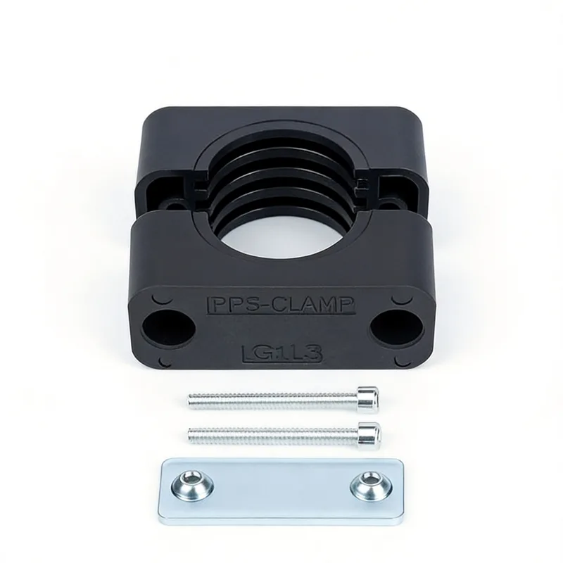
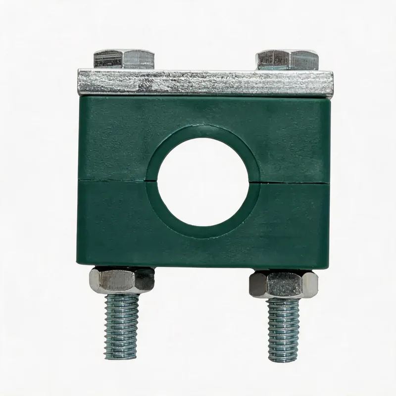
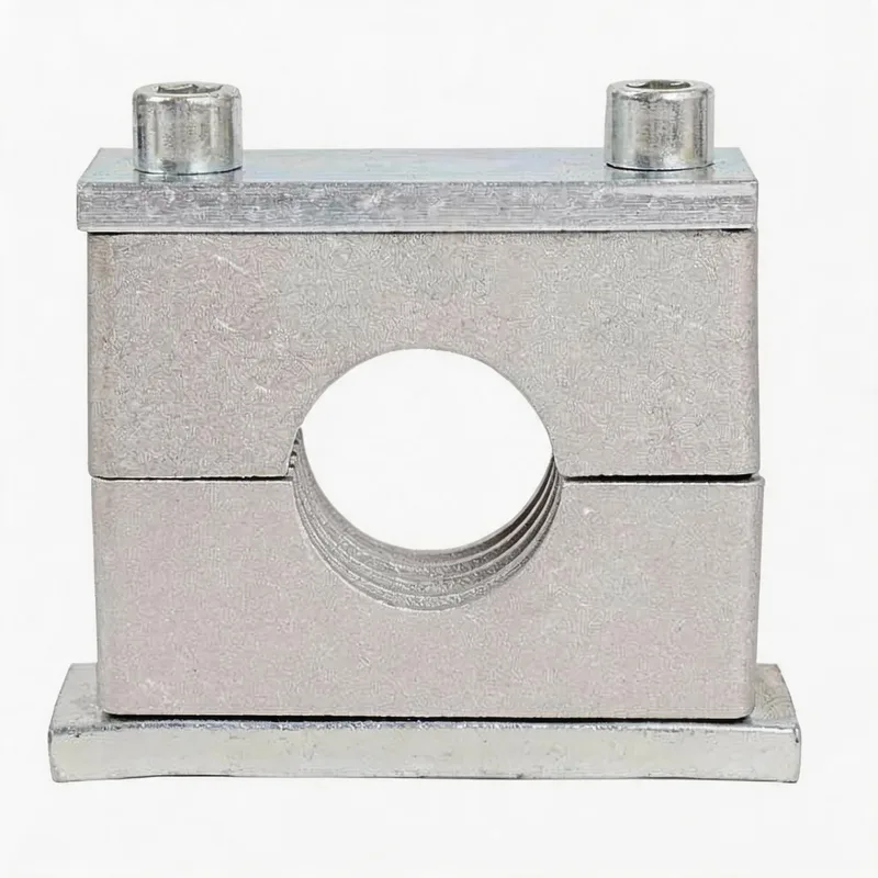
Related product photos
Key points
- Bolt preload degrades during shutdown through corrosion-induced section loss, thread seizure and thermal-cycle creep — never assume bolts retain their original preload
- PP and PA clamp bodies exposed to outdoor UV for 2+ years during shutdown may be brittle — tap-test (tap with a small hammer; a dull thud indicates brittleness, a sharp ring indicates integrity)
- Hydrotest before recommissioning applies the heaviest load the supports will see — inspect and repair supports before hydrotest, not after
- CUI under insulation is invisible until the insulation is removed — budget for insulation removal and re-application at clamp locations during shutdown inspection
| Shutdown Duration | Likely Degradation | Inspection Scope | Typical Replacement Rate |
|---|---|---|---|
| 3–6 months | Surface rust on zinc bolts; minor preload relaxation; no polymer degradation | Visual inspection + spot re-torque check (10% of clamps) | < 2% of bolts |
| 6–18 months | Significant zinc consumption on exposed bolts; possible CUI initiation under insulation; early UV damage on PP | Visual all clamps + re-torque all outdoor + CUI spot-check (remove insulation at 20% of clamp locations) | 5–10% of bolts; 2–5% of PP bodies outdoor |
| 18 months – 3 years | Zinc coating may be fully consumed; CUI active under wet insulation; PP bodies brittle; thread seizure on carbon steel bolts | Full inspection all clamps + torque-test all bolts + CUI check all insulated clamp locations + tap-test all outdoor PP bodies | 15–30% of bolts; 10–20% of outdoor PP bodies |
| 3–5+ years | Assume full zinc loss on outdoor bolts; CUI likely on insulated lines in 60–150 °C range; PP bodies cracked or crumbling; weld plates may have significant corrosion | Complete re-survey of all pipe supports as a new condition assessment — treat as a brownfield re-engineering exercise | 30–60% of bolts; 20–40% of PP bodies; 5–15% of weld plates |
Replacement rates are indicative and depend heavily on the original material specification, coating quality, and severity of the local environment. Plants in dry inland deserts degrade much slower during shutdown than plants in humid coastal environments.
Bolt corrosion assessment: surface rust vs structural loss
Not all rust on a bolt means the bolt must be replaced. Surface rust (a thin, loose, orange layer on the zinc coating) indicates that the sacrificial zinc is doing its job — the zinc is corroding preferentially to protect the underlying steel. As long as there is still zinc remaining under the rust, the bolt retains its structural integrity. You can verify this by wire-brushing the rust off: if shiny zinc is visible underneath, the bolt is serviceable. If the wire brush reveals dark grey or black steel underneath the rust, the zinc is fully consumed and the steel is now corroding. At this stage, measure the bolt diameter with callipers — if it has lost more than 0.5 mm of diameter (0.25 mm per side), the cross-sectional area reduction is significant enough to reduce the bolt tensile capacity, and the bolt should be replaced. For M8 bolts, 0.5 mm loss represents approximately 12% area reduction; for M10, approximately 10%. Also check for pitting: a bolt with localised deep pits (visible as small holes in the surface) is weaker than the average diameter suggests, because the pit acts as a stress concentration point for fatigue cracking. Replace any bolt with visible pitting deeper than 0.3 mm.
Polymer body degradation: visual signs and the tap test
Polymer pipe clamp bodies (PP and PA) degrade through a combination of UV exposure, thermal ageing and chemical attack during shutdown. The visible signs of degradation, in order of severity: (1) Surface chalking — the surface becomes powdery white or grey, indicating photo-oxidation of the outer layer. At this stage, the bulk material is still sound. (2) Surface cracking — fine cracks appear on the sun-facing surface. The material is weakened but may still function if the cracks are shallow (< 0.5 mm). (3) Deep cracking or crazing — cracks penetrate into the wall thickness. The clamp body is compromised and must be replaced. (4) Brittleness — the material has lost its ductility and will fracture under impact or bolt preload. The tap test is a quick field method: strike the clamp body lightly with a small ball-peen hammer or the handle of a screwdriver. A sound clamp produces a sharp, ringing tone. A degraded clamp produces a dull thud, and a severely degraded clamp may chip or crack from the impact. Any clamp that chips, cracks or produces a dull sound should be replaced. Do not rely on visual inspection alone for black PA bodies — carbon black masks surface degradation that is visible in natural-colour material, so the tap test is essential for black clamps.
CUI inspection at clamp locations
Corrosion under insulation develops silently during shutdown because the conditions that cause it — moisture trapped against a metal surface in the 60–150 °C temperature range — persist even when the plant is not operating. During shutdown, the pipe cools to ambient temperature, but if the insulation has already absorbed moisture (from rain, humidity, deluge testing, or fire-water system leaks), the corrosion continues at ambient temperature, just more slowly. The clamp location is a high-risk CUI point because the clamp body creates a gap between the insulation and the pipe where water collects, and the bolt holes in the weld plate or rail provide additional crevice sites. To inspect for CUI at clamp locations: (1) Remove the insulation cladding and insulation material for at least 300 mm on each side of the clamp. (2) Visually inspect the pipe surface, the clamp contact area, the weld plate and the bolt threads for corrosion pitting, wall thinning or deposits. (3) If corrosion is found, measure the remaining pipe wall thickness with an ultrasonic thickness gauge at the clamp contact points and at the 6-o-clock position (bottom of pipe, where water pools). (4) Wire-brush the bolt threads and attempt to run a nut — if the nut cannot be run by hand, the thread is damaged and the bolt should be replaced. (5) After inspection, dry all surfaces, apply corrosion-inhibiting primer, install new insulation and re-seal the cladding joints to prevent future moisture ingress.
Preload recovery: re-torque procedure before restart
Before hydrotest and restart, every pipe clamp bolt should be checked for adequate preload. The procedure: (1) Clean the bolt head and nut with a wire brush to remove corrosion products — you need a clean hex surface for the torque wrench to grip without slipping. (2) Attempt to loosen the bolt by one-quarter turn — if it breaks free easily, the preload has been lost and the bolt needs re-torquing. If it cannot be loosened (seized), the corrosion has bonded the threads and the bolt must be replaced because there is no way to verify the remaining preload. (3) If the bolt breaks free normally, re-tighten to the specified torque value using a calibrated torque wrench. Apply the torque in two stages: 50% first, then 100%, to ensure even loading. (4) If a threadlocker was originally used, clean the old threadlocker from the threads with a solvent and apply fresh threadlocker before re-tightening. (5) Mark the bolt head and nut with a witness mark (a paint stripe across the bolt-nut-clamp junction) so that any future rotation is immediately visible. (6) Record the torque value, bolt condition (reused or replaced) and date for each clamp in the inspection report. For large plants with thousands of clamps, prioritise: inspect all clamps on safety-critical lines first (high-pressure, high-temperature, flammable or toxic service), then proceed to utility and low-risk lines.
Load changes between shutdown and restart
The load distribution on pipe supports changes between the shutdown (cold) and operating (hot) conditions. During operation, hot pipes expand and push against fixed supports, transferring load laterally. During shutdown, the pipes cool, contract and settle into their cold position, which may differ from the installed (ambient) position if the system was originally hot-adjusted. Supports that carried high loads during operation may be lightly loaded during shutdown, while guides and anchors that were designed to resist expansion forces now sit idle. When the plant restarts, the pipes heat up and expand again, and supports must be in good enough condition to carry the returning loads. If a support degraded during shutdown (a corroded bolt, a cracked clamp body, a failed weld), it may carry the shutdown load adequately but fail when the full operating load returns. This is why inspection must assess capacity against the operating load, not the shutdown load. Similarly, if the hydrotest precedes restart, the test load (pipe full of water) may exceed the operating load on gas or steam lines — the inspection must verify that supports can carry the hydrotest weight, which is often the governing load case.
Recommissioning inspection checklist
Use this checklist for each pipe support location before hydrotest and restart: (1) Visual condition of clamp body — check for cracks, chalking, brittleness (tap test for polymer bodies), deformation, missing parts. Record: pass / replace. (2) Bolt condition — wire brush, check for section loss (measure diameter if corroded), check thread engagement (run nut test), check for pitting. Record: pass / re-torque / replace. (3) Bolt preload — loosen one-quarter turn and re-torque to specification. Record torque value. Apply new threadlocker or witness mark. (4) Weld plate and bracket — check for corrosion, crack at weld toe, deformation, anchor bolt tightness. Record: pass / repair / replace. (5) Insulation condition at clamp (insulated lines only) — remove insulation, inspect for CUI, measure pipe wall thickness if corrosion found, replace insulation and re-seal. Record: no CUI / CUI found (detail extent and remaining wall). (6) Clamp-to-pipe fit — verify pipe is correctly seated in clamp bore, not resting on the bolt or riding on one side. Adjust if needed. (7) Thermal expansion provisions — verify guided supports allow axial pipe movement (not seized by corrosion or debris), verify fixed supports are secure. (8) Sign-off — inspector name, date, clamp tag number or location reference, disposition (pass / conditional pass with follow-up / fail — replace before hydrotest). Compile all records into a pipe support inspection register and include it in the recommissioning documentation package.
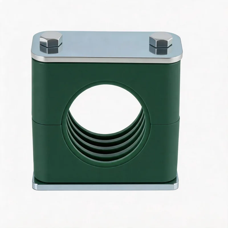
Related WeiQue series
Recommended reading
References
These pages summarize public standard metadata and industry application information. They do not reproduce the paid DIN standard text.