
Specifying a pipe clamp correctly is not a single decision but a sequence of linked decisions, each of which depends on the application. This handbook brings the whole sequence together in one place: it walks through every dimension of DIN 3015 pipe clamp selection — choosing the series, sizing to the pipe, selecting the body material, choosing and tightening the fasteners, deciding the mounting method, confirming the load rating and spacing, accommodating thermal movement, controlling vibration, and protecting against corrosion — and explains the engineering logic behind each so that the decisions reinforce rather than contradict each other. It is written as a structured overview and map: each section summarises one domain and points to where the detailed treatment lives, so an engineer can use it to work through a complete specification or to find the right deeper guide for a specific question. The goal is that by the end you can take a line list and produce a defensible clamp schedule, understanding why each choice was made and how it connects to the others.
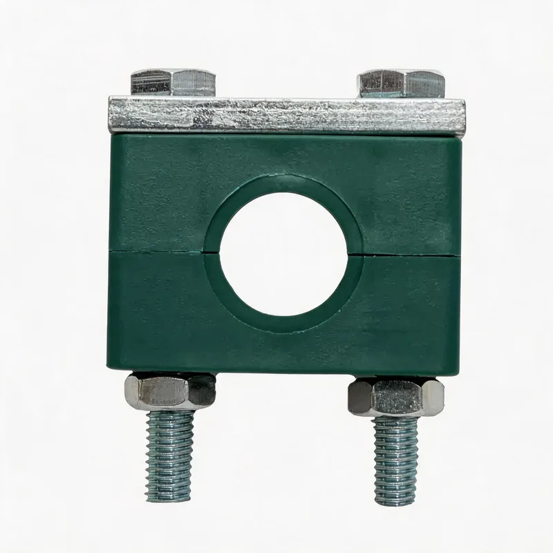
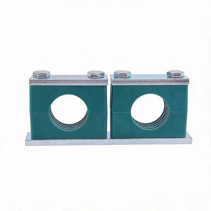
Related product photos
Key points
- Clamp selection is a sequence: series → size → material → fasteners → mounting → load/spacing → thermal → vibration → corrosion, each step depending on the application
- The decisions are linked — material affects temperature limit, mounting affects load path, spacing affects vibration — so they must be made together, not in isolation
- Order by measured pipe OD and DIN 3015 part/series, not by nominal bore — the single most common specification error
- The end product is a clamp schedule: for each support, the series, size, material, fastener, mounting and function, traceable to the application requirements
| Decision Step | Key Input | Main Output | Depends On |
|---|---|---|---|
| 1. Series | Load, vibration, line count | Part 1 / 2 / 3 | Application duty |
| 2. Size | Measured pipe OD | Clamp group | Series (P1/P2 differ) |
| 3. Body material | Temperature, chemistry, UV | PP / PA / metal | Environment |
| 4. Fasteners | Corrosion, load, vibration | Grade, finish, locking, torque | Body material, environment |
| 5. Mounting | Structure, load, adjustability | Rail / weld plate / beam clamp | Load path, structure |
| 6. Load & spacing | Pipe weight, span, dynamics | Spacing, rated clamp | Series, vibration, thermal |
The steps are presented in order, but they interact. A choice late in the sequence (e.g. close spacing for vibration control) can change an earlier one (a lighter series may now suffice). Treat the sequence as iterative: work through it once, then check the decisions are consistent.
Step 1 — Choosing the series: standard, heavy or twin
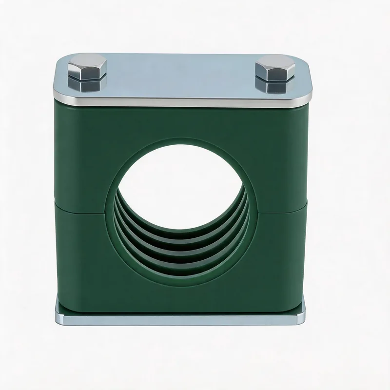
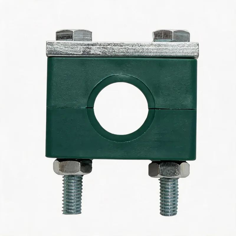
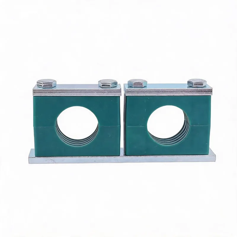
The first decision is which DIN 3015 series fits the duty. Part 1 (standard series) covers the majority of general industrial and hydraulic pipework: it uses a polymer body to grip the pipe and is suited to normal loads and moderate vibration. Part 2 (heavy series) has a larger, stronger body for higher loads, higher vibration, larger pipes and more demanding service — it is the choice when the standard series would be marginal. Part 3 (twin series) holds two parallel pipes in one clamp body, useful for paired hydraulic lines or where two services run together. The choice is driven by the load the support must carry, the vibration severity, the pipe size and the line configuration. A useful way to decide is to start with the standard series as the default and step up to the heavy series when the load, vibration or pipe size pushes beyond what the standard series comfortably handles. This step sets the framework for everything that follows, because the series determines the available size groups, the bolt sizes and the body construction. For the detailed comparison and a selection matrix, see the dedicated DIN 3015 standard guide and the standard-versus-heavy comparison.
Step 2 — Sizing to the pipe by outside diameter
With the series chosen, the clamp size is set by the pipe outside diameter (OD). DIN 3015 organises clamps into numbered groups, each covering a range of pipe OD, and the correct group is the one whose range contains the measured OD of the pipe. The single most important rule here is to size by the actual outside diameter, not by the nominal bore (DN or NPS): nominal pipe size refers to the bore and does not equal the OD, so ordering a clamp by DN can give the wrong size entirely. Measure the pipe OD (or take it from the pipe data sheet) and select the group for that OD in the chosen series — remembering that Part 1 and Part 2 can use different group/bolt arrangements for the same OD. For insulated pipe, the clamp must fit the outside diameter of the insulation and cladding, not the bare pipe, which moves the sizing to a much larger group. Getting the size right is what makes the clamp grip correctly: too large and the pipe is loose, too small and it will not close. The detailed sizing method, the nominal-size-to-OD relationship and measuring for replacements are covered in the dedicated sizing guides.
Step 3 — Selecting the body material
The clamp body material is chosen for the operating environment: temperature, chemical exposure, UV and outdoor weathering, and the mechanical duty. Polypropylene (PP) is the economical default for general indoor service up to about 80 °C, with good resistance to many chemicals. Polyamide (PA, nylon) tolerates higher temperatures and tougher mechanical duty, and within PA the grade matters — PA12 for wet, humid and outdoor service because of its low moisture absorption, glass-filled PA66 for higher temperature and stiffness. For outdoor and high-UV environments, a UV-stabilised (black) grade is essential, because unprotected polymer degrades quickly in sunlight. Above the polymer temperature limits, or near heat sources, metal bodies (aluminium or steel) are used. For cushioned and anti-vibration duty, a rubber-insert clamp adds damping and the insert material (NBR for oil, EPDM for water and outdoor, FKM for chemicals and heat) is selected to suit the fluid and environment. The material choice interacts with later steps: it sets the temperature limit, influences the maximum tightening torque, and determines the chemical and UV resistance. The material guides cover PP-versus-PA, the PA grade comparison, temperature limits, rubber inserts and high-temperature options in detail.
Step 4 — Choosing and tightening the fasteners
Each clamp closes with a bolt (or two), and the fastener choice covers grade, finish, size, locking and tightening. The bolt size follows from the clamp series and group — it is defined by the clamp, not chosen freely. The grade and finish follow from the duty and environment: class 8.8 carbon steel with a suitable coating for general service, stainless A2-70 or A4-80 where corrosion demands it, with hot-dip galvanized or Dacromet for outdoor and abrasive environments. Crucially, the fastener material should be galvanically compatible with the clamp body and pipe to avoid galvanic corrosion. Where vibration or thermal cycling is present, a positive bolt-locking method (disc-spring washers, wedge-locking washers, serrated-flange bolts or threadlocker) is needed because friction alone will not hold. Tightening matters too: the bolt must be torqued to the correct value, and for stainless bolts the torque is lower than carbon steel and lubrication is needed to avoid galling — and for polymer-bodied clamps the clamp body, not the bolt, often sets the maximum torque. The fastener guides cover bolt strength classes, torque values, stainless torque and galling, locking methods, galvanic compatibility, marking and the bolt-size-to-clamp relationship.
Step 5 — Deciding the mounting method
The clamp must attach to a supporting structure, and the mounting method is chosen for the structure available, the load, and how much adjustability is needed. The common DIN 3015 mounting methods are: weld plate, where the clamp is bolted to a plate welded to the structure — strong and permanent, suited to fixed points and high loads; rail mounting, where clamps slide on a mounting rail and are held with channel nuts — adjustable, ideal where layout may change or many clamps run in a line; and beam clamps or brackets, where the clamp attaches to existing steelwork without welding. The mounting determines the load path from the pipe through the clamp into the structure, and the whole path must be rated for the load, because the weakest link governs — a strong clamp on a thin weld plate is limited by the weld. The mounting also delivers the support function from the stress analysis: a guide needs a mounting that allows axial sliding, an anchor needs a rigid weld-plate or equivalent. The mounting guides cover the methods, rail-versus-weld-plate, the accessories and BOM, and how block clamps compare to U-bolts.
Step 6 — Confirming load rating and spacing
With series, size, material and mounting chosen, the load and spacing are confirmed. The load each clamp carries is the weight of the pipe span it supports — the pipe, the fluid, the insulation — plus any lateral or dynamic loads from wind, seismic or vibration. The clamp and its whole mounting must be rated for this load with an appropriate safety factor, checking the load rating correctly (ultimate versus working load, axial versus lateral capacity) and the weakest link in the load path. The spacing between clamps is set so that each clamp's load stays within rating and the pipe does not sag or vibrate excessively; for simple lines a support-spacing table gives the maximum span, while demanding lines take the spacing from a stress analysis. Spacing and load are linked: closer spacing reduces the load per clamp and raises the pipe's natural frequency (helping with vibration), at the cost of more clamps. This step may send you back to revise an earlier one — if the load is high, a heavier series or closer spacing may be needed. The load-rating and spacing guides, and the stress-analysis and vibration guides, cover the calculations and the trade-offs.
Step 7 — Accommodating thermal movement
If the line operates hot or cold, thermal movement must be designed into the support scheme. A pipe changes length with temperature, and the clamps must let it expand and contract in a controlled way rather than constraining it everywhere. This is done by assigning each support a function: fixed (anchor) points that hold the pipe and divide it into sections, guide points that let the pipe slide axially while restraining it sideways, and rest points that carry weight while allowing movement. The clamp at each point must physically deliver its function — an anchor clamp rigidly fixed, a guide clamp allowing axial sliding (often on a slide plate). Getting this wrong — clamping every point rigidly — generates large thermal stresses and can pull supports off the structure or overload connected equipment. Cryogenic and high-temperature lines are extreme cases needing particular attention to contraction or expansion and to material behaviour at the temperature. The thermal-expansion, fixed-and-guided-point, and cryogenic guides cover the movement strategy in detail, and the stress-analysis guide explains how the functions are assigned.
Step 8 — Controlling vibration
Where the line is near a vibration source — pumps, compressors, rotating machinery — or carries pulsating or high-velocity flow, vibration control is part of the support design. Uncontrolled vibration drives fatigue, which cracks pipework, loosens bolts and fractures clamps over time, so it must be addressed rather than tolerated. The two levers are spacing and damping. Reducing the clamp spacing raises the pipe span's natural frequency, moving it away from the excitation frequency to avoid resonance — the most common and effective fix. Cushioned (rubber-insert) clamps add damping that absorbs vibration energy and isolate machine vibration from the pipe. Where vibration is present, bolt-locking is essential to stop the joints working loose. Vibration interacts strongly with spacing (Step 6) and with material (Step 3, the cushion insert), so it is often considered alongside them. High-flow gas systems can suffer acoustic-induced vibration, a high-frequency phenomenon needing specialist piping assessment. The vibration-and-fatigue guide and the anti-vibration cushioned-clamp guide cover the mechanisms and remedies.
Step 9 — Protecting against corrosion
The final dimension is corrosion protection, matched to the environment over the design life. Indoor dry service is undemanding; outdoor, coastal, marine, chemical and washdown environments are progressively more aggressive. The clamp body polymer is inherently corrosion-resistant, so the corrosion concern centres on the metal parts — the bolts, nuts, weld plates and any metal clamp body. The protection is delivered by material and coating: zinc plating for mild service, hot-dip galvanized or Dacromet for outdoor and abrasive environments, and stainless steel (A4-80 / 316L, or duplex for the most aggressive coastal and marine service) where chlorides demand it. Two specific mechanisms need attention: galvanic corrosion, avoided by matching the metals in the assembly or isolating them; and corrosion under insulation (CUI) on insulated lines, addressed with stainless hardware and inspection access. The corrosion choice connects back to the fastener choice (Step 4) and the material choice (Step 3). The corrosion-protection, galvanic-compatibility, stainless-marine and desert-environment guides cover the mechanisms and the material and coating selection for each environment.
Bringing it together: the clamp schedule and RFQ
The output of working through the sequence is a clamp schedule: for every support location, the series, size group, body material, fastener grade and finish, mounting method, support function, and the load it carries — each traceable to the application requirements. Because the decisions are linked, the schedule is best produced by working through the sequence once and then checking consistency: does the chosen material suit the temperature; is the fastener compatible with the body and pipe; does the mounting deliver the required function; is the clamp rated for the load at the chosen spacing; does the layout accommodate thermal movement and control vibration; is the corrosion protection right for the environment. When the schedule is internally consistent, it is a defensible specification. To request a quotation, send the line list with, for each line, the pipe OD and material, the operating temperature and pressure, the fluid, the load and span or required spacing, the support function where known, the mounting structure, the environment, and any project specification or code — the more complete the information, the more precisely the supplier can confirm the series, size, material, fastener and mounting for each clamp and return a schedule and price. This handbook is the map; the linked detailed guides are the territory; together they take a line list to a complete, engineered clamp specification.
Related WeiQue series
Recommended reading
References
These pages summarize public standard metadata and industry application information. They do not reproduce the paid DIN standard text.