
Selecting and placing pipe supports well requires understanding what the piping system is doing mechanically — and that is the subject of pipe stress analysis. Pipe stress analysis is the engineering discipline that checks whether a piping system can safely carry all the loads it will experience over its life: the weight of the pipe and its contents, the forces from thermal expansion and contraction, internal pressure, and occasional loads such as wind, seismic events and fluid transients. The support system is central to this analysis, because supports carry the weight, restrain or guide thermal movement, and react the occasional loads — and where supports are placed and how they are configured directly changes the stresses in the pipe and the loads on connected equipment. This guide is a practical introduction for engineers who select and install pipe clamps and need to understand the analysis that drives the support requirements: the load types, how thermal expansion is managed through anchors and guides, the role of allowable stress and the ASME B31 piping codes, the functions different supports perform, and crucially, when a simple support-spacing table is sufficient and when a formal computer stress analysis is required. It is not a substitute for a stress analysis, but it explains the framework so that support selection is done with understanding rather than by rote.
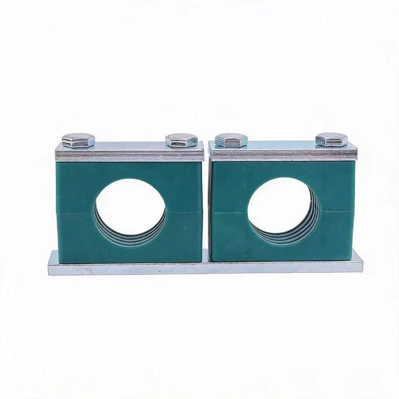
Related product photos

Key points
- Pipe stress analysis checks the pipe against four load categories: sustained (weight + pressure), thermal expansion, occasional (wind/seismic/transient), and their combinations
- Supports have distinct functions — rest, guide, anchor — and the analysis assigns each support a function that the clamp must physically provide
- Thermal expansion is managed by deliberately fixing the pipe at chosen points and letting it slide at others, not by clamping everything rigidly
- A span table suffices for simple, ambient-temperature, low-criticality lines; hot, large, high-criticality or equipment-connected lines need a formal stress analysis
| Load Category | What It Includes | Effect on Supports | Code Basis |
|---|---|---|---|
| Sustained | Pipe weight, fluid weight, insulation, internal pressure | Sets the vertical (gravity) load each support carries | Limited by allowable stress (e.g. ASME B31.3) |
| Thermal (expansion) | Stress from constrained thermal growth/contraction | Drives the anchor/guide layout and movement allowance | Displacement stress range, code-limited |
| Occasional | Wind, seismic, water hammer, relief reaction | Adds lateral/dynamic loads to certain supports | Higher allowable stress for short-duration events |
| Equipment nozzle loads | Forces/moments the pipe imposes on pumps, vessels, turbines | Support layout must keep nozzle loads within limits | Vendor nozzle allowables (e.g. API 610/686) |
These categories are checked separately and in combination against code-defined allowable stresses. The support system is the main design variable the engineer adjusts to keep every category within its allowable — moving, adding or re-functioning supports changes the stress distribution.
What pipe stress analysis is and why supports are central to it
Pipe stress analysis is the process of verifying that a piping system will not fail or behave unacceptably under the loads it experiences. It checks three broad things: that the stresses in the pipe wall stay within the limits the design code permits, that the pipe does not deflect or move excessively, and that the forces and moments the pipe imposes on connected equipment (pump nozzles, vessel connections, turbine flanges) stay within what that equipment can tolerate. All three of these depend directly on the support system. The supports carry the weight and so determine the sustained stress and deflection; they restrain or permit thermal movement and so determine the thermal stress; and by holding the pipe in position they determine how much load is transmitted to the end equipment. This is why support design is not a separate activity bolted on after the pipe is routed — it is an integral part of the stress analysis. The stress engineer adjusts the support scheme (where supports go, what each one does) as the primary tool to bring the system within all its limits. When the analysis is complete, it produces a support schedule that specifies, for each support location, the load it must carry and the function it must perform. The pipe clamp is the hardware that delivers that function at that location.
The load categories: sustained, thermal, occasional
Stress analysis organises the loads on a pipe into categories that are checked against different allowable limits, because they act in different ways. Sustained loads are those always present: the weight of the pipe, the fluid, the insulation and any attached components, plus the effect of internal pressure. Sustained loads act continuously and are checked against the material's allowable stress; if exceeded, the pipe can sag, overstress or eventually fail by gross deformation. Thermal (or expansion) loads arise when the pipe changes temperature and its natural growth or shrinkage is constrained by the supports and end connections; the resulting stress is a displacement-driven stress that is checked against an allowable stress range (it is self-limiting and treated differently from sustained stress). Occasional loads act for short periods: wind on outdoor pipe, seismic acceleration during an earthquake, the reaction from a relief valve discharging, or the impulsive force of water hammer. Because they are brief, codes permit a higher allowable stress for occasional loads in combination with sustained loads. The analysis checks each category and the relevant combinations against the corresponding allowable. The support system has to satisfy all of them simultaneously: a support might be sized by the sustained weight load but also has to react an occasional seismic load and accommodate thermal movement — and the clamp at that location must be able to do all three.
Thermal expansion and the anchor-guide-fixed system
Thermal expansion is often the dominant consideration in stress analysis of hot (or cold) lines, and managing it is largely a matter of support strategy. When a pipe heats up it grows; a long steel line can grow many millimetres or even centimetres over its length. If that growth is fully constrained at both ends, enormous thermal stress and force are generated. The art of pipe support is to let the pipe expand in a controlled way: the line is divided into sections by anchors (points where the pipe is fully fixed and cannot move in any direction), and within each section the growth is directed and absorbed. Guides allow the pipe to slide along its axis while preventing it from moving sideways, channelling the expansion toward a flexible element. Expansion loops, offsets or expansion joints absorb the growth between anchors. Rest (or sliding) supports carry weight while letting the pipe move freely. The analysis decides where to place anchors and guides so that the thermal stress and the loads on equipment stay within limits, and it assigns each support a function accordingly. For the person selecting clamps, the key consequence is that not every support is the same: an anchor clamp must rigidly fix the pipe, a guide clamp must restrain it laterally while letting it slide axially, and a rest clamp must carry weight without over-constraining movement. Clamping every support rigidly — the intuitive but wrong approach — defeats the expansion strategy and can overstress the pipe.
Support functions: rest, guide, anchor and specials
Stress analysis assigns each support one of a small set of functions, and the clamp or support hardware must physically deliver it. A rest (or sliding) support carries vertical weight but lets the pipe move horizontally in any direction — it restrains only downward. A guide restrains the pipe laterally (perpendicular to its axis) while allowing it to slide along the axis; guides channel thermal movement and prevent buckling or sideways drift. An anchor fully fixes the pipe at a point, preventing translation in all three directions and usually rotation too; anchors divide a line into independently expanding sections and provide a fixed reference. A line stop (or axial stop) restrains movement along the pipe axis at a point while permitting lateral movement — the complement of a guide. Beyond these, there are specials: spring hangers and supports that carry weight while allowing vertical thermal movement (used where the pipe rises or falls thermally and a rigid support would either lift off or overload), and snubbers or dampers that allow slow thermal movement but lock up against sudden dynamic loads like seismic or water hammer. For clamp selection, the practical mapping is: rest and guide functions are commonly delivered by DIN 3015 clamps (a standard clamp on a slide plate for a guide, a clamp that allows axial movement for a rest); anchors require a rigid clamp firmly fixed to a strong structure; and the specials (springs, snubbers) are dedicated devices that a clamp attaches to rather than replaces. Reading the support function from the support schedule tells you what kind of clamp arrangement is needed.
Allowable stress and the ASME B31 codes
The yardstick against which all the calculated stresses are compared is the allowable stress defined by the governing piping design code. In much of the world the ASME B31 series sets these rules: B31.1 for power piping, B31.3 for process piping, B31.4 and B31.8 for pipelines, and others for specific industries; Europe uses EN 13480 for industrial piping with a similar framework. These codes define, for each material and temperature, a basic allowable stress, and they specify how the sustained, thermal and occasional stresses are calculated and what multiple of the allowable each may reach. For example, sustained stress is limited to the basic allowable; the thermal expansion stress range is limited to a separately calculated allowable range; and occasional loads combined with sustained may be permitted to reach a higher factor of the allowable because they act briefly. The code also sets the rules for the support spacing tables that many engineers use for simple lines — those tables are derived from limiting the sustained bending stress and deflection to code-acceptable values. For the support and clamp engineer, the relevance is that the load each support must carry, and the spacing between supports, ultimately trace back to keeping these code stresses within the allowable. When a project specification cites a B31 code, it is invoking this whole framework, and the support schedule that results is the code-compliant answer that the clamps must implement.
Equipment nozzle loads: why support layout protects pumps and vessels
One of the most important outcomes of stress analysis, and one that directly drives support placement, is keeping the loads the pipe imposes on connected equipment within the equipment's tolerance. A pipe connected to a pump, a pressure vessel, a turbine or a heat exchanger imposes forces and moments on that equipment's nozzle through the weight of the pipe and especially through thermal expansion. Rotating equipment in particular — pumps and turbines — is sensitive: excessive nozzle load can distort the casing, misalign the shaft, cause bearing wear, vibration and seal failure. Equipment manufacturers publish allowable nozzle loads (for pumps, often based on standards such as API 610; the broader installation practice is covered by API 686), and the stress analysis must demonstrate that the piping does not exceed them. The support system is the primary means of achieving this: by carrying the pipe weight close to the equipment so the nozzle does not have to, and by placing anchors and guides so that thermal expansion is directed away from the equipment rather than into its nozzle. A common and serious field problem is a pipe whose weight or thermal growth is dumped onto a pump nozzle because the nearby support was missing, badly placed or set to the wrong function. For the clamp engineer, this underlines why the support near equipment is critical and why its specified function and load must be delivered exactly — a clamp near a pump nozzle is protecting an expensive, sensitive machine.
Support spacing tables: the simple case
For simple piping, a full computer stress analysis is unnecessary, and the support spacing can be taken from a standard table. Support spacing tables (such as those in ASME B31.1, MSS SP-58 and many engineering handbooks) give a recommended maximum span between supports as a function of pipe size, for straight runs of standard steel pipe carrying water or gas at ambient temperature. These tables are derived by limiting two things: the bending stress in the pipe due to its own weight and contents (kept within the code allowable), and the midspan deflection or sag (kept small enough to avoid pooling and to look acceptable, often a few millimetres). The result is a safe spacing for ordinary horizontal runs. Using a span table is appropriate when the line is straight or simple, operates at or near ambient temperature so thermal expansion is negligible, carries a routine fluid, is not connected directly to sensitive equipment, and is not subject to significant vibration or occasional loads. Many utility and service lines fit this description, and for them a span table plus good practice (support near changes of direction, near heavy valves, and at branch connections) is entirely sufficient. The spacing from the table tells the clamp engineer how far apart to place the clamps; the clamp load is then simply the weight of the supported span.
When a formal stress analysis is required
A formal computer stress analysis (using software such as CAESAR II, AutoPIPE or similar) is required when the piping is no longer simple enough for a span table to capture its behaviour. The common triggers are: significant operating temperature, hot or cold, so that thermal expansion generates important stresses and movements that must be analysed; large pipe diameter, where the weight, the loads and the consequences of failure are high; connection to sensitive equipment such as pumps, compressors, turbines or air-cooled exchangers, where nozzle loads must be demonstrated to be within allowables; high pressure or hazardous, flammable or toxic service, where the criticality justifies rigorous analysis; complex geometry with many changes of direction, branches and equipment, where the interaction of loads is not captured by simple rules; significant occasional loads such as seismic, wind on large outdoor lines, or transient and pulsation loads; and cases where a code or client specification mandates analysis regardless. In these situations the analysis produces the support schedule — the location, load and function of every support — and the clamp selection follows from it directly. The clamp engineer should never try to second-guess or simplify a support that came from a formal analysis; if a support is specified as an anchor carrying a defined load, the clamp arrangement must deliver exactly that. When in doubt about whether a line needs formal analysis, the conservative and correct course is to involve a piping stress engineer, because the cost of an unanalysed failure on a critical line far exceeds the cost of the analysis.
From support schedule to clamp selection
The output of the stress analysis that matters to the clamp engineer is the support schedule: a list of every support location with its design load and its function (rest, guide, anchor, line stop, spring, etc.), and often the design temperature, the pipe size and the required movement allowance. Turning this into a clamp selection follows a clear path. For each support, read the function and select a clamp arrangement that delivers it: a rest or guide is typically a DIN 3015 clamp configured to allow the required sliding direction (on a slide plate or guided rail), while an anchor is a rigidly fixed clamp on a strong base. Read the design load and confirm the clamp and its mounting are rated for it with the appropriate safety factor — checking the whole load path (clamp body, bolt, weld plate, structure), since the weakest link governs. Read the design temperature and movement and select the clamp body material and the insert (cushioned, PTFE slide, etc.) to suit. Apply the corrosion and environment requirements to the material and coating. Finally, document the selection against the support schedule so that each installed clamp is traceable to the analysed requirement. Done this way, support selection is a direct, defensible translation of the stress analysis into hardware. The clamp is not chosen in isolation — it is chosen to fulfil a specified function and load at a specified location, which is exactly what the stress analysis defined.
Related WeiQue series
Recommended reading
References
These pages summarize public standard metadata and industry application information. They do not reproduce the paid DIN standard text.