
Vibration is one of the most common causes of pipework and pipe support failure, and it is also one of the least well understood at the installation level. A pipe that vibrates is not merely a nuisance: sustained vibration drives fatigue, and fatigue cracks pipework, loosens bolted joints, fractures clamp bodies and eventually causes leaks or failures. The support system — the clamps and their spacing — is the primary tool the engineer has to control vibration, because it sets the stiffness and damping of the pipe and determines where the pipe's natural frequencies lie relative to the frequencies that excite it. This guide brings together the engineering behind pipe vibration and fatigue: where the excitation comes from, why resonance amplifies it, how repeated stress cycles cause fatigue failure, how damping and support stiffness control the response, and how the practical levers of clamp type and spacing are used to keep a piping system out of trouble. It is written for engineers who need to understand why a pipe is vibrating and how to fix it properly rather than repeatedly re-tightening a failing support.
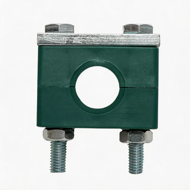
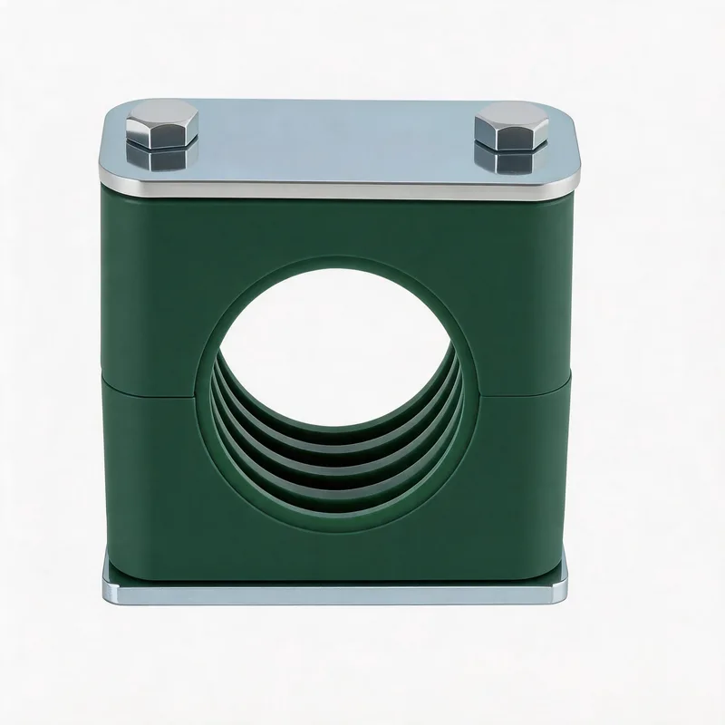
Related product photos
Key points
- Vibration causes fatigue: repeated stress cycles, even well below the static yield strength, accumulate damage and crack pipework and clamps over time
- Resonance is the danger: when an excitation frequency matches a pipe natural frequency, the vibration amplitude is amplified many times over
- Clamp spacing sets the natural frequency: shorter spans raise the natural frequency, moving it away from low-frequency excitation
- Cushioned (damped) clamps absorb vibration energy; rigid clamps transmit it — the choice depends on whether you need isolation or restraint
| Excitation Source | Typical Frequency | Mechanism | Control Approach |
|---|---|---|---|
| Reciprocating pump/compressor | Running speed × plunger count (e.g. 5–30 Hz) | Pressure pulsation in fluid + mechanical vibration | Pulsation dampener + closer clamp spacing + cushioned clamps |
| Centrifugal pump | Vane-pass frequency (running speed × vanes) | Flow pulsation at the impeller | Avoid resonance via spacing; cushioned clamps near pump |
| Flow-induced (turbulence, vortex) | Broadband / velocity-dependent | Turbulent energy and vortex shedding excite the pipe | Stiffen with closer spacing; add damping |
| Rotating machinery (general) | 1× and 2× running speed | Unbalance and misalignment transmit through structure | Isolate with cushioned clamps; avoid resonant spans |
| Water hammer / transient | Impulsive (single events) | Sudden valve closure sends a pressure wave | Robust restraint at bends; adequate clamp strength |
Identifying the excitation frequency is the first diagnostic step — it tells you what the pipe is responding to and whether resonance is likely. Many vibration problems are a coincidence between an excitation frequency and a pipe natural frequency that can be broken simply by changing the clamp spacing.
Where pipe vibration comes from: excitation sources
Vibration is always driven by an excitation source — energy entering the pipe at some frequency. The most common sources in industrial pipework are: reciprocating pumps and compressors, which produce strong pressure pulsation in the fluid at a frequency equal to the running speed multiplied by the number of plungers or cylinders, plus mechanical vibration of the machine itself; centrifugal pumps, which produce flow pulsation at the vane-pass frequency (running speed times the number of impeller vanes); rotating machinery generally, which transmits vibration at one and two times running speed through unbalance and misalignment; flow-induced vibration, where turbulence and vortex shedding inside the pipe excite it across a band of frequencies that depends on flow velocity; and transient events such as water hammer, where a sudden valve closure sends an impulsive pressure wave through the system. To control vibration you must first identify the source and its frequency, because the frequency determines whether the pipe will resonate and which control measure will work. A vibration survey — measuring the vibration amplitude and frequency spectrum on the pipe — reveals the dominant frequency, which can then be matched to a known excitation source. Without this step, vibration remediation is guesswork.
Natural frequency and resonance
Every span of pipe between two supports has one or more natural frequencies — the frequencies at which it tends to vibrate freely if disturbed, set by its mass, stiffness and the support conditions at each end. The natural frequency of a pipe span rises with stiffness (a stiffer or shorter span has a higher natural frequency) and falls with mass (a heavier pipe, or one full of dense fluid, has a lower natural frequency). Resonance occurs when an excitation frequency coincides with a natural frequency of the pipe span. At resonance, each push from the excitation arrives in step with the pipe's own motion and adds to it, so the vibration amplitude builds up to many times what the same excitation would produce away from resonance — limited only by damping. Resonance is the root cause of most severe pipe vibration problems: a small pulsation that would be harmless becomes destructive because the span happens to resonate at the pulsation frequency. The engineering goal is therefore to keep the pipe's natural frequencies away from the excitation frequencies, ideally with a separation margin (a common rule of thumb is to keep the natural frequency at least 20–30% above or below the excitation frequency). Because the natural frequency depends on span length, and span length is set by clamp spacing, the clamp layout is the primary means of placing the natural frequency where it needs to be.
The fatigue mechanism: why vibration cracks metal
Fatigue is the progressive, localised damage that occurs when a material is subjected to repeated cycles of stress, even when each individual cycle is well below the stress that would cause the material to yield or break in a single application. Vibration is precisely this kind of repeated cyclic stress: every oscillation flexes the pipe and its supports, applying a small stress cycle, and a vibrating pipe accumulates these cycles at the vibration frequency — tens of cycles per second, millions per day. Fatigue damage begins as microscopic crack initiation at a stress concentration (a weld, a thread, a clamp edge, a surface defect), then the crack grows a little with each cycle until it reaches a critical size and the remaining section fails suddenly. The relationship between the stress amplitude and the number of cycles to failure is described by the S-N curve (stress versus number of cycles): higher stress amplitude means fewer cycles to failure, and below a certain stress amplitude (the fatigue limit, for materials that have one) the part can endure effectively unlimited cycles. The practical implication for pipe supports is profound: a vibration amplitude that seems small can still cause failure if it is allowed to continue for enough cycles, because the damage accumulates. This is why a chronically vibrating pipe must be fixed, not tolerated — and why the fix must reduce the stress amplitude (by reducing the vibration) rather than just managing the symptoms.
Damping versus rigid support: isolation or restraint
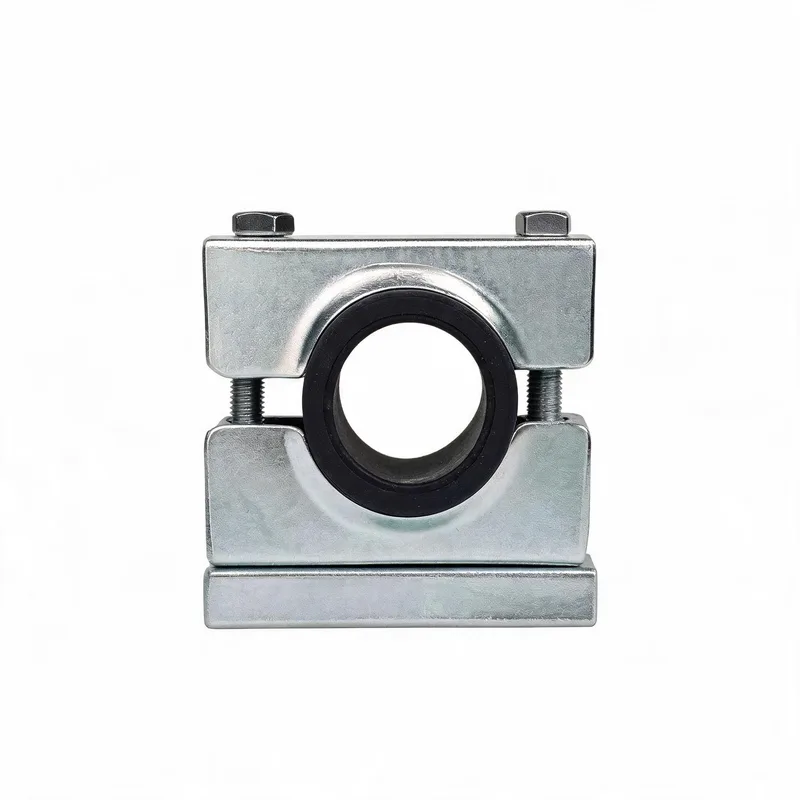
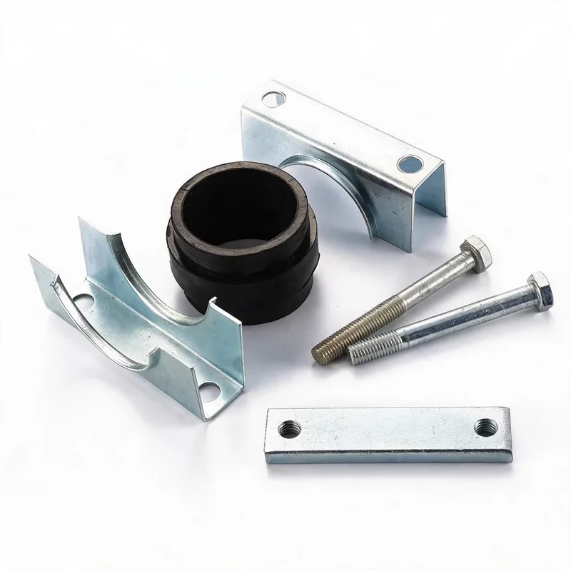
There are two fundamentally different strategies for handling vibration at a support, and choosing the right one depends on what you are trying to achieve. A rigid clamp grips the pipe firmly to a stiff structure, restraining it and raising the assembly's stiffness and natural frequency. Rigid support is the right choice when you want to push the natural frequency up and away from a low-frequency excitation, or when you need to firmly restrain the pipe against a force such as water hammer or short-circuit-style impulsive loads. A cushioned (damped) clamp incorporates an elastomer insert (such as EPDM or NBR rubber) between the pipe and the rigid clamp body. The elastomer does two things: it absorbs and dissipates vibration energy (damping), converting some of the mechanical energy to heat each cycle and thereby reducing the resonant amplification; and it isolates the pipe from the structure, reducing the transmission of vibration between them. Cushioned support is the right choice when you want to isolate machine vibration from the pipe (or pipe vibration from the structure), or to add damping that reduces the peak amplitude at resonance. The two strategies can be combined in a system: rigid restraint where the pipe must be anchored or where high natural frequency is needed, and cushioned isolation near vibration sources. The key is to be deliberate — choosing rigid where isolation is needed, or cushioned where firm restraint is needed, makes the problem worse.
How clamp spacing shifts the natural frequency
The single most powerful lever the installation engineer has over pipe vibration is the clamp spacing, because the natural frequency of a pipe span depends strongly on its length. For a given pipe, the natural frequency of a span is inversely proportional to the square of the span length — halving the span length raises the natural frequency by a factor of four. This means that adding intermediate clamps to shorten the spans is a very effective way to raise a pipe's natural frequency above a troublesome excitation frequency. Consider a pipe that resonates with a pump running at 25 Hz because its span natural frequency happens to be near 25 Hz: reducing the span (by adding a clamp in the middle) raises the natural frequency well above 25 Hz, breaking the resonance and dramatically reducing the vibration amplitude. This is why the standard remedy for a resonating pipe is often simply to add supports and reduce the spacing. The relationship works in both directions, but in practice the move is almost always to shorten spans (raise the frequency), because most damaging excitation in pipework is at relatively low frequencies and raising the pipe's natural frequency above them is the reliable fix. When using spacing to control vibration, check the resulting natural frequency against the excitation frequency and aim for a separation margin so that normal operating variation does not bring the system back into resonance.
Bolted-joint loosening and clamp fatigue under vibration
Vibration attacks not only the pipe but also the support itself, in two ways. First, vibration loosens bolted joints. Transverse vibration in particular causes the bolted clamp joint to undergo tiny relative movements that progressively undo the preload, so a clamp bolt that was correctly tightened works loose over time. Once the bolt loses preload, the clamp grips the pipe less firmly, the pipe moves more, the vibration increases, and the loosening accelerates — a self-reinforcing failure. This is why vibration-exposed clamps must use a positive bolt-locking method (disc-spring washers that maintain tension, wedge-locking washers that resist rotation, serrated-flange bolts, or threadlocker) rather than relying on friction alone, and why they need periodic re-torque checks. Second, vibration fatigues the clamp body and the mounting. The same cyclic stress that fatigues the pipe also cycles the clamp body, the weld plate and the bracket, and over enough cycles these can crack — particularly at stress concentrations such as weld toes and bolt holes. A polymer clamp body flexing under vibration can develop fatigue cracks; a weld plate can crack at the weld toe; a bracket can fail at a bend. The remedy is the same as for the pipe: reduce the vibration at source (spacing, damping, isolation) so the cyclic stress on the support drops below the level that causes fatigue, and use bolt-locking to keep the joint tight so the support continues to do its job.
Acoustic-induced vibration and high-frequency fatigue
A specialised but important category is acoustic-induced vibration (AIV), which occurs in high-flow gas systems downstream of pressure-reducing devices such as relief valves, control valves and restriction orifices. The rapid pressure drop generates intense high-frequency acoustic energy (sound power) in the gas, which excites the pipe wall at high frequencies — typically hundreds to thousands of hertz, far higher than the mechanical excitation from pumps. At these high frequencies the pipe wall flexes in shell modes (the cross-section distorts) rather than beam modes (the span bends), and the resulting stress concentrates at small discontinuities such as small-bore branch connections, welds and supports. Because the frequency is so high, the number of stress cycles accumulates extremely fast — millions of cycles in hours — so AIV can cause fatigue failure very quickly, sometimes within days of start-up, typically at the weld of a small branch connection. AIV is primarily a piping design issue (managed by limiting the acoustic power, improving branch connection geometry and avoiding unsupported small-bore connections), but the support system is part of the picture: supports must not introduce stress concentrations, and small-bore connections near AIV sources need robust bracing rather than being left to cantilever. If a high-flow gas system shows signs of high-frequency vibration or has experienced small-bore fatigue cracking, AIV should be assessed by a piping engineer, because the ordinary spacing-and-damping remedies for low-frequency mechanical vibration do not address the shell-mode, high-frequency mechanism.
Diagnostic-to-remedy workflow
A systematic approach to a pipe vibration problem: (1) Confirm the symptom — visible movement, audible noise, loosening bolts, or fatigue cracks — and locate where it is worst along the line. (2) Identify the excitation source and its frequency: which machine, what running speed, what pulsation or flow condition; a vibration measurement giving the dominant frequency is invaluable here. (3) Estimate or measure the pipe span natural frequency and compare it to the excitation frequency — if they are close, resonance is the cause. (4) Choose the remedy that addresses the mechanism: if resonance, change the clamp spacing to shift the natural frequency away from the excitation (usually shorten the spans to raise it); if transmitted machine vibration, add cushioned isolation near the source; if pulsation from a reciprocating machine, address the pulsation at source (dampener) as well as the supports; if high-frequency gas AIV, escalate to a piping engineer. (5) Implement bolt-locking on all affected clamps so the fix is not undone by loosening. (6) Verify after the change — re-measure the vibration to confirm the amplitude has dropped and the resonance is broken. (7) Inspect for existing fatigue damage — a pipe that has vibrated for a long time may already have fatigue cracks initiated, which must be found and repaired even after the vibration is controlled. Throughout, fix the root cause (the vibration) rather than the symptom (the loose bolt or cracked clamp), because managing symptoms on a vibrating pipe is an endless cycle of re-tightening and replacing until the underlying vibration is brought under control.
Related WeiQue series
Recommended reading
References
These pages summarize public standard metadata and industry application information. They do not reproduce the paid DIN standard text.